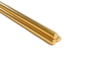
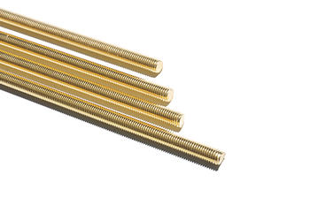
The equipment is refitted by a lathe, the workpiece is rotated, and the cutter head and knurled tool holder are moved. Remove the lathe tool holder part, install the milling head and self-made tool holder on the slide plate, install the knurling tool on the tool holder, and place the tool holder in front of the milling cutter head. The left end of the workpiece is clamped with a chuck, the tailstock is removed at the right end, and a bracket with a longer hollow tube is installed, so that a longer material can be clamped at a time (equivalent to more than twice the length of a milling), and the milling part can be cut and processed. Reduce end material waste.
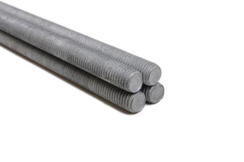
When specially designed, the polished rod drives the lead screw to rotate in the nut. The left end of the lead screw is equipped with a spring chuck, and the workpiece rotates to the left to feed. Both the polished rod and the lead screw are processed by hollow tubes (to reduce end material waste). Because the middle is suspended for a long time, you can consider supporting it with an auxiliary bracket.
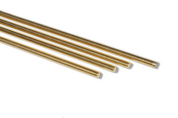
The clamping device of the knurling knife. The knurling tool device of the two designs is the same, but the connection part between the support frame and the machine tool is different. Machining a hole on the support frame, milling grooves and through holes on the opposite side of the processed part through the center line of the hole: the width of the groove is the same as the knurled tool holder, the depth is the same as the height of the tool holder, and the bottom of the groove close to the slot is perpendicular to the root Milling a narrow slot is convenient for the fine iron filings extruded by the knurling to flow out, preventing the knurling wheel from stagnating and jamming. The knurled knife is pressed by a quick-change cover, and the knurled knife handle is tightened by a screw rod with a plum blossom handle. The round steel is knurled after passing through the guide sleeve, and then is milled at a high speed to realize the two processes at one time. The guide sleeve is made of quenched and tempered tool steel, with an opening milled on it, and the length is flat with the end surface of the bracket. The guide sleeve positioning pin hole, the assembly screw and the bracket are matched with each other. Make sure that the opening is directly on the center line of the groove.
 英语
英语 中文简体
中文简体 阿拉伯语
阿拉伯语 德语
德语 西班牙语
西班牙语